Hydraulic Pump Maintenance for Combines
Maintain your combine's hydraulic system. Learn pump operation, fluid checks, component replacement, and sourcing options for hydraulic parts.
A combine harvester's hydraulic system powers the header, reel, unloading auger, steering, and numerous auxiliary functions. When hydraulic performance degrades, the symptoms—slow header response, weak unloading, erratic steering—can cascade into lost harvest hours. Understanding how the system works, what fails, and how to maintain it keeps the machine productive and helps you source the right replacement components when maintenance is due.
This guide covers hydraulic pump operation, fluid management, failure diagnosis, and parts identification for John Deere and Case IH combines. It is intended for operators, shop technicians, and parts buyers who need practical maintenance knowledge alongside sourcing guidance.
Overview of the Combine Hydraulic System
A modern combine uses multiple hydraulic circuits, each sized for its function:
- Implement circuit — drives the header raise/lower, reel speed, and platform tilt.
- Steering circuit — provides power-assisted or hydrostatic steering.
- Unloading circuit — powers the grain tank auger and related conveyance.
- Auxiliary and cooling circuits — fan drives, cooling package, and supplemental functions.
Pressure and flow are managed through a combination of pumps (one or more), control valves, relief valves, filters, a reservoir, and cooler. Each circuit has defined pressure limits; exceeding them activates relief valves that dump flow back to tank, preventing component damage at the cost of lost work capacity. Beyond the primary hydraulic circuits, the combine belt drive system powers additional auxiliary functions; coordinating maintenance across both systems ensures uninterrupted harvest performance.
Hydraulic Fluid Maintenance
Fluid Types and Specifications
Manufacturers specify hydraulic fluid by viscosity grade, additive package, and operating temperature range. Brand fluid families include John Deere Hy-Gard and Case IH Hy-Tran, but the required product and specification vary by machine and market. Using a fluid that does not meet the machine-specific specification can affect lubrication, seal compatibility, and valve operation.
Always confirm the correct specification in the operator's manual for the specific machine model and production year. Specifications can change between model generations.
Contamination Risks
Hydraulic fluid contamination is a major risk for pump and valve wear. Sources include:
- Ingress through worn cylinder seals or breather caps.
- Internal generation from component wear particles.
- Moisture condensation during temperature cycling.
- Introduction during service when ports are left uncapped.
Do not apply one cleanliness target to every combine. Use the limit stated in the machine's technical manual or the hydraulic component manufacturer's specification. A laboratory particle count and fluid analysis can help track contamination trends when interpreted against that machine-specific limit.
Drain Intervals
Follow the operator's manual for the exact machine and fluid specification. Filter and fluid intervals differ by model, hydraulic circuit, fluid used, and operating conditions. Fluid analysis may justify earlier service, but it should not be used to extend an interval beyond the manufacturer's instructions without qualified technical guidance.
Understanding Hydraulic Pumps
Pump Types
Combines use several pump architectures:
- Gear pumps — simple, tolerant of contamination, used for lower-pressure circuits (charge pumps, fan drives). Wear shows as reduced flow at pressure.
- Axial piston pumps — variable displacement, high efficiency, used for main implement and hydrostatic circuits. More sensitive to contamination but deliver precise flow control.
- Vane pumps — occasionally used in steering circuits. Moderate pressure capability with smooth flow characteristics.
Pressure Settings and Relief Valves
Each pump circuit has a maximum system pressure set by a relief valve. These settings are specified in the technical manual and should be verified with a calibrated gauge during routine service. A relief valve that opens too early causes weak performance; one that opens too late risks hose, fitting, or component failure.
Common Hydraulic System Failures
Pressure Loss
Symptoms: slow actuator movement, inability to reach full force. Causes include worn pump internals, leaking relief valve, internal cylinder bypass, or a failed priority valve. Diagnosis starts with a pressure test at the pump outlet compared to the specified relief setting.
Flow Reduction
Symptoms: actuators move but at reduced speed. Causes include pump wear (reduced volumetric efficiency), restricted suction line, clogged filter with bypass open, or incorrect fluid viscosity at operating temperature.
Wear Patterns
Pumps wear predictably. Gear pumps develop clearance between gear faces and the wear plates. Piston pumps wear at the barrel-to-valve-plate interface and at piston-to-bore clearance. Elevated case drain flow is a reliable early indicator of piston pump wear—measure it against the manufacturer's new and condemn limits.
Identifying Hydraulic Parts for Replacement
When a hydraulic component needs replacement, accurate identification prevents costly mismatches:
- Read the OEM number stamped or labeled on the pump housing, valve body, or motor casing. Record it completely, including prefix and suffix characters.
- Note flow rate and pressure ratings printed on the nameplate or specified in the parts catalog for that position.
- Identify the mounting interface—bolt pattern, shaft spline count, rotation direction, and port size/orientation.
- Check the parts catalog by machine model and serial number to confirm the correct part number for your production range. Our John Deere cross-reference guide details this process step by step.
Hydraulic components are not interchangeable by appearance alone. Two pumps with identical displacement but different pressure ratings, shaft configurations, or port arrangements will not install or perform correctly.
OEM vs. Aftermarket Hydraulic Components
Hydraulic components operate under high pressure and tight tolerances. The OEM-vs-aftermarket decision carries more weight here than for simpler wear parts:
Seal Compatibility
Aftermarket seal kits must match the OEM material specification (Viton, Buna-N, polyurethane) and dimensional tolerances. Incorrect seal material can swell, harden, or fail under system pressure and fluid chemistry.
System Pressure Requirements
An aftermarket pump or motor must meet the same maximum continuous and peak pressure ratings as the OEM component. Under-rated components risk catastrophic failure under load.
When Aftermarket Is Appropriate
Aftermarket suppliers offer remanufactured pumps and new-manufacture replacements, sometimes described as meeting an OEM specification. Treat that description as a claim to verify. Check the exact cross-reference, displacement, pressure and speed ratings, rotation, shaft and port configuration, test record, and warranty before considering the component for an older or supply-constrained machine. For more detail on the OEM-vs-aftermarket decision framework, see our comparison guide.
Preventive Maintenance Schedule
Seasonal Checks (Pre-Harvest)
- Inspect all hoses and fittings for abrasion, cracking, leaks, and secure routing.
- Check hydraulic fluid level and condition (color, smell, clarity).
- Replace hydraulic filters per the service interval or if the restriction indicator is triggered.
- Verify cylinder rod condition—pitting or scoring accelerates seal wear.
- Test system pressure against specification with a calibrated gauge.
Operating Hour Milestones
| Interval | Action |
|---|---|
| Daily or pre-shift | Check fluid level, visible leaks, hose damage, and warning indicators |
| At each scheduled service | Inspect hoses, fittings, cooler, reservoir breather, and filter restriction indicator |
| At the model-specific filter interval | Replace the specified hydraulic or hydrostatic filters and record part numbers |
| At the model-specific fluid interval | Drain and refill with the manual-specified fluid and procedure |
| As indicated by testing | Compare pressure, flow, case drain, and fluid analysis with the technical manual limits |
Adjust intervals based on operating conditions. Dusty environments, extreme temperatures, and heavy-duty cycles (continuous unloading, frequent header cycling) accelerate wear.
For maintenance supplies and hydraulic component sourcing, our guides on air and fuel filter maintenance and fuel pump options cover related service categories.
When you need a specific hydraulic pump, motor, valve, or seal kit identified and quoted for your combine, submit a replacement-part quote request with the OEM number, machine model, serial number, and any nameplate data from the component.
Official references
- John Deere Parts and Service
- John Deere Combine Maintenance Resources
- Case IH Parts and Service
- Case IH Operator's Manuals
John Deere, Case IH, and their model names are trademarks of their respective owners. FieldFit Parts is not affiliated with or endorsed by John Deere or Case IH. OEM numbers and model names are used for identification and compatibility reference only. Always confirm the current OEM catalog record, service manual specifications, and the machine's actual configuration before ordering or installing a replacement part.
Continue to the catalog
Related Combine Parts Catalogs
Move from lookup guidance to published brand-specific parts. Search by the complete OEM or reference number and confirm the machine details before ordering.
Related Parts
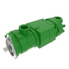
FFP-JD-R01427
Hydraulic Pump for John Deere - Replaces OEM AXE57337
Quote-only replacement part for OEM AXE57337. Confirm final fitment with your model or original part number.
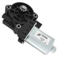
FFP-JD-R01210
Adjustment Hydraulic Motor for John Deere - Replaces OEM AXE13287
Quote-only replacement part for OEM AXE13287. Confirm final fitment with your model or original part number.
FFP-JD-R01283
Hydraulic Motor for John Deere - Replaces OEM AH141859
Quote-only replacement part for OEM AH141859. Confirm final fitment with your model or original part number.
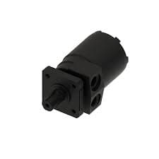
FFP-JD-R01284
Hydraulic Motor for John Deere - Replaces OEM AH149717
Quote-only replacement part for OEM AH149717. Confirm final fitment with your model or original part number.
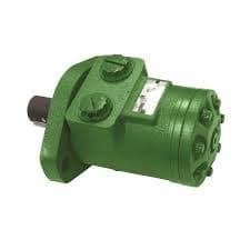
FFP-JD-R01285
Hydraulic Motor for John Deere - Replaces OEM AH159155
Quote-only replacement part for OEM AH159155. Confirm final fitment with your model or original part number.
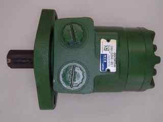
FFP-JD-R01424
Hydraulic Motor for John Deere - Replaces OEM AH206399
Quote-only replacement part for OEM AH206399. Confirm final fitment with your model or original part number.
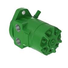
FFP-JD-R01282
Hydraulic Motor for John Deere - Replaces OEM AH228405
Quote-only replacement part for OEM AH228405. Confirm final fitment with your model or original part number.